
Today, as data centers move towards the 400G/800G era, MPO fiber optic jumpers have become the preferred solution for high-speed optical interconnect systems with their high-density integration and plug-and-play characteristics. This article will deeply analyze its technical points and selection logic to help you build an efficient and reliable network architecture.
1. MPO jumper: Redefine fiber connection efficiency
Core Values:
·Space Revolution: Single jumper integrates 8/12/16/24 core fiber (mainstream 12 cores), saving 75% space than traditional LC jumper;
·Zero Welding Deployment: Factory pre-termination design, direct plug-in and unplug on site, reducing construction complexity and failure rate;
·Multi-scene adaptation: supports data center cabinet interconnection, 5G fronthaul network, FTTH fiber to home and other high bandwidth scenarios.
Technical evolution:
From 40G to 400G networks, MPO jumpers continue to meet bandwidth requirements through core number upgrades (such as MPO-16 supports 400G SR8), becoming a "vascular level" component of supercomputing centers and AI clusters.
2. Choose the four core dimensions of MPO jumper
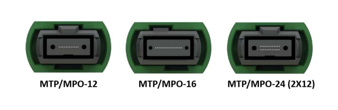
- Number and layout of fiber cores
|
Type |
Typical Application |
Signal Channel Utilization |
|
MPO-12 |
100G SR4 (4Tx + 4Rx) |
8/12 cores (middle 4 cores idle) |
|
MPO-16 |
400G SR8 (8Tx + 8Rx) |
16/16 cores fully utilized |
|
MPO-24 |
High-density trunk cabling |
24/24 cores |
Selection suggestions: MPO-16 is preferred for 400G network, and MPO-12 is more cost-effective for 100G network.
- Connector male and female types
Male: with guide needle (PIN needle), achieving physical accurate alignment;
Female: contains guide holes and must be used with males;
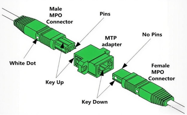
Golden Rule: Male and female must be paired! Male-to-male-to-male-to-male connection can cause fiber misalignment or even damage.
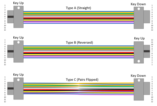
- Keying Direction and Polarity Management
Keying function: The top positioning key ensures that the insertion direction is unique (key up/down);
Polarity scheme:
|
Type |
Fiber Mapping Rule |
Applicable Scenario |
|
A-Type |
1→1, 2→2(Straight-through) |
Simple point-to-point topology |
|
B-Type |
1→12, 2→11(Full cross) |
Data center backbone |
|
C-Type |
1→2, 2→1(Adjacent flip) |
Specific device interconnections |
- Fiber performance grade (OM standard)
|
Fiber Type |
Core/Cladding Diameter |
Jacket Color |
Supported Applications |
|
OM1 |
62.5μm/125μm |
Orange |
100 Mbps Ethernet |
|
OM2 |
50μm/125μm |
Orange |
1 Gbps Ethernet |
|
OM3 |
50μm/125μm |
Aqua |
10 Gbps Ethernet |
|
OM4 |
50μm/125μm |
Aqua / Purple |
40/100 Gbps Short Reach |
|
OM5 |
50μm/125μm |
Lime Green |
40/100/200/400 Gbps (SWDM) |
Key points: 100G network requires at least OM4, and choosing OM5 for future upgrades is more scalable.
3. Technical genes of MPO connectors
★Birth background: developed by NTT in Japan, standardized by IEC-61754-7 and TIA-604-5;
★Precision structure:
Ferrule (ceramic/metal) → guide needle → spring pressurized → dust cap
★Ensure that the error of 72-core optical fiber is <0.5μm;
★Start position identification: The side white dot marks the fiber number 1 position to avoid polarity confusion.
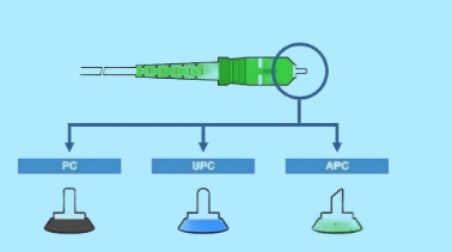
4.End face processing and performance indicators
Comparison of grinding process
|
Type |
Ferrule Endface Geometry |
Return Loss |
Typical Applications |
|
UPC |
Dome-shaped polishing |
≥50 dB |
Standard data center links |
|
APC |
8° angled polishing |
≥60 dB |
5G fronthaul / CATV networks |
Performance red line:
Insertion loss: multimode ≤0.6dB, singlemode ≤0.75dB (low-loss version requires ≤0.35dB)
Durability: The loss change after 500 times of plugging and unplugging is ≤0.2dB.
|
Parameter |
APC |
UPC |
PC |
|
Ferrule Endface Geometry |
8° angled polishing |
Dome-shaped polishing |
Spherical polishing |
|
Return Loss |
-60dB (Higher) |
-50dB |
-40dB |
|
Color Coding |
Singlemode: Green Multimode: Beige |
Singlemode: Blue Multimode: Beige |
Singlemode:Blue Multimode: Beige |
|
Primary Applications |
Telecom (FTTH, PON) |
Data center, conventional telecommunications |
Legacy low-demand scenarios |
|
Common Models |
LC/SC/ST/FC/E2000/MPO |
LC/SC/ST/FC/E2000/MPO |
LC/SC/ST/FC |
5. Future-oriented deployment suggestions
1)Space reservation: 30% redundant ports are reserved for cabinet wiring racks to deal with expansion;
2) Hybrid architecture: single-mode MPO (long distance) is used for backbone links, and multi-mode MPO (low cost) is used for cabinets;
3)Acceptance standards: Suppliers are required to provide insertion and loss test reports to ensure that each core has a loss meets the standards.
Conclusion
MPO jumpers have evolved from "optional accessories" to the "core artery" of high-density networks. By mastering the three key points of core number planning, polarity matching and performance verification, you can build a "zero error" optical link for the 100G/400G system.
【Technical Team Tips】If you need customized MPO solution or performance testing support, please contact our technical team or click Raisefiber.com
Post time: Jul-29-2025