
Jumper cables are used to make the final connection from patch panels to transceivers, or they are used in the centralised cross connect as a means of connecting two independent backbone links. Jumper cables are available with LC connectors or MTP connectors depending on whether the infrastructure is serial or parallel. Generally, jumper cables are short length assemblies because they only connect two devices within the same rack, however in some cases jumper cables can be longer, such as "middle of row" or "end of row" distribution architectures.
RAISEFIBER manufactures jumper cables which are optimised for the "in-rack" environment. Jumper cables are smaller and more flexible than conventional assemblies and connectivity is designed to allow highest packing density and easy, fast access. All of our jumper cables contain bend optimised fiber for enhanced performance under tight bending conditions, and our connectors are colour coded and identified based on base type and fiber type.
• Colour coded connector boots by fiber-count
• Ultra compact cable diameter
• Bend optimised fiber and flexible construction
• Available as 8Fiber, -12Fiber or -24Fiber types
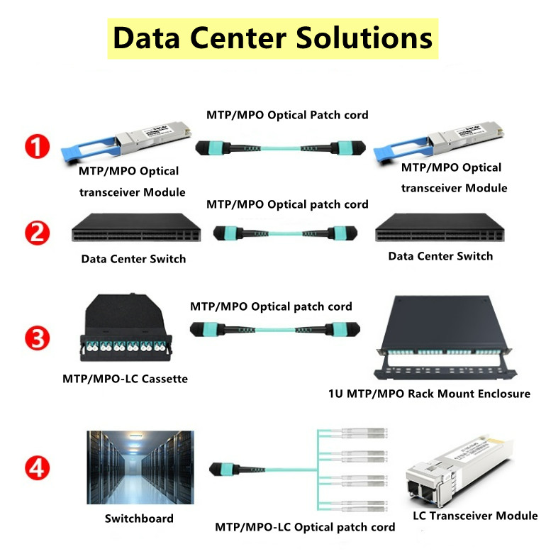
The MTP fiber system is a truly innovative group of products that moves fiber optic networks into the new millennium. MTP fiber and MTP assemblies take their name from the MTP “Multi-fiber Termination Push-on” connector, designed and introduced as a high performance version of the MPO connectors. MTP does interconnect with the MPO connectors. Each MTP contains 12 fibers or 6 duplex channels in a connector smaller than most duplex connections in use today. MTP connectors allow high-density connections between network equipment in telecommunication rooms. It is the same size of a SC connector but since it can accommodate 12 fibers, it provides up to 12 times the density, thereby offering savings in circuit card and rack space.
MTP technology with multi-fiber connectors offers ideal conditions for setting up high-performance data networks in data centers to handle future requirements. This technology makes scaling and migration to network operation with 40/100 Gigabit Ethernet easier and more efficient. There are many MTP products in the market now, such as MTP fiber cables, MTP connectors,
Cable management: MTP Modules and Harnesses in Data Center
Traditional optical cable management such as duplex patch cords and duplex connector assemblies work well in application-specific, low-port-count environments. But as port counts scale upwards and system equipment turnover accelerates, these cable managements become unmanageable and unreliable. Deploying a modular, high-density, MTP-based structured wired cabling system in the data center will significantly increase response to data center moves, adds and changes (MACs). Knowledge of MTP modules and MTP harnesses will be provided in this blog.
Introduction to MTP Modules and Harnesses
An obvious benefit to deploying a MTP-based optical network is its flexibility to transmit both serial and parallel signals. MTP to duplex connector transition devices such as modules and harnesses are plugged into the MTP trunk assemblies for serial communication. MTP Modules are typically used in lower-portcount break-out applications such as in server cabinets. MTP harnesses provide a significant increase in cabling density and find value in high port count break-out situations such as SAN Directors. The built-in modularity of the solution provides flexibility to easily configure and reconfigure the cabling infrastructure to meet current and future networking requirements. MTP harnesses and modules can be exchanged or completely removed from the backbone network to quickly adapt to data center MACs.
MTP Modules in Data Centers
MTP modules typically are placed in a housing located in the cabinet rack unit space. Here the MTP trunk cable is plugged into the back of the module. Duplex patch cords are plugged into the front of the module and routed to system equipment ports. Integrating the MTP modules cabling solution into the data center cabinet can enhance the deployment and operation of the data center cabling infrastructure. As shown in the figure below, integrating the MTP modules into the cabinet vertical manager space maximizes the rack unit space available for data center electronics. MTP modules are moved to the cabinet sides where they snap into brackets placed between the cabinet frame and side panel. Properly engineered solutions will allow MTP modules to be aligned with low-port-count system equipment placed within the cabinet rack unit space to best facilitate patch cord routing.
Unveil Polarity of MTP/MPO Multi-Fiber Cable Solutions
With widespread deployment of 40G and 100G networks, high-density MTP/MPO cable solutions are also become more and more popular. Unlike traditional 2‐fiber configurations LC or SC patch cords, with one send and one receive, 40G & 100G Ethernet implementations over multimode fibers use multiple parallel 10G connections that are aggregated. 40G uses four 10G fibers to send and four 10G fibers to receive, while 100G uses ten 10G fibers in each direction. MTP/MPO cable can hold 12 or 24 fibers in a connector, which greatly facilitates the upgrade to 40G and 100G networks. However, since there are so many fibers, the polarity management of the MTP/MPO cable may be a problem.
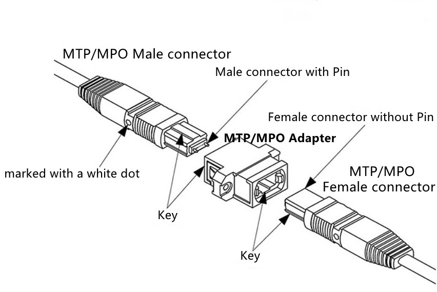
Structure of MTP/MPO Connectors
Before explaining the polarity, it is important to learn about the structure of MTP/MPO connector first. Each MTP connector has a key on one side of the connector body. When the key sits on top, this is referred to as the key up position. In this orientation, each of the fiber holes in the connector is numbered in sequence from left to right. We will refer to these connector holes as positions, or P1, P2, etc. Each connector is additionally marked with a white dot on the connector body to designate the position 1 side of the connector when it is plugged in.
Three Polarity of MTP/MPO Multi-Fiber Cable
Unlike traditional duplex patch cables, there are three polarity for MTP/MPO cables: polarity A, polarity B and polarity C.
As show in the pictures
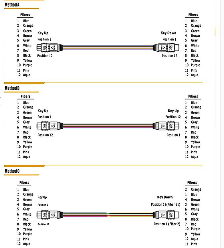
Polarity A
Polarity A MTP cables use a key up, key down design. Therefore, the position 1 of one connector is corresponding to the position 1 of another connector. There is no polarity flip. Therefore, when we use polarity A MTP cable for connection, we must use A-B duplex patch cables on one end and A-A duplex patch cables on the other end. Since in this link, Rx1 must connect to Tx1. If we don’t use A-A duplex patch cable, according to the design principle of polarity A MTP cable, fiber 1 may transmit to fiber 1, that is to say Rx1 may transmit to Rx1, which may cause errors.
Polarity B
Polarity B MTP cables use a key up, key up design. Therefore, the position 1 of one connector is corresponding to the position 12 of another connector. Therefore, when we use polarity B MTP cable for connection, we should use a A-B duplex patch cables on both ends. Since the key up to key up design help to flip the polarity, which makes fiber 1 transmit to fiber 12, that is the Rx1 transmits to Tx1.
Polarity C
Like the polarity A MTP cables, polarity C MTP cables also use a key up, key down design. However, within in the cable, there is a fiber cross design, which makes the position 1 of one connector is corresponding to the position 2 of another connector. when we use polarity C MTP cable for connection, we should use a A-B duplex patch cables on both ends. Since the cross fiber design help to flip the polarity, which makes fiber 1 transmit to fiber 2, that is the Rx1 transmits to Tx1.
Post time: Sep-03-2021